
I still remember the first time I was handed a set of millwork shop drawings. I stared at the pages filled with lines, numbers, and strange symbols, pretending to understand while secretly feeling lost. I had seen finished millwork, beautiful cabinets, custom trim, and intricate paneling, but translating those final pieces from a technical drawing? That felt overwhelming.
If you’ve ever felt the same way, trust me, you’re not alone. Millwork shop drawings might look complicated at first, but once you break them down, they become much easier to understand.
So, what exactly are they? Simply put, millwork shop drawings are detailed plans that guide the fabrication and installation of custom woodwork. They show dimensions, materials, and construction details to confirm everything is built and installed correctly. Without these drawings, miscommunication can lead to costly mistakes and delays.
But here’s the good news: you don’t need to be a drafter to understand them. You just need to know what to look for. Before diving into a set of millwork shop drawings, let’s first break down their key elements.
Key Elements Of Millwork Shop Drawings
Generally, millwork shop drawings include different views and key details to communicate the design. Let’s break them down:
Title Block
The title block is like the label of a millwork shop drawing. It contains important project details, including the company name, project title, and contact information. It also shows the sheet number, scale, and who created or checked the drawing.
If changes are made, the revision section tracks updates. There are also check boxes to indicate whether the drawing is for approval, fabrication, or final records. The title block keeps the project organized and makes sure everyone understands the purpose of the drawing.
Plan Views

A plan view provides a top-down look at the millwork layout. It shows how different components fit together, including cabinets, countertops, and other built-ins. This view includes dimensions, labels, and symbols to specify materials and construction details.
For example, in this nurse station plan, we can see the countertop layout, joint lines, and material callouts. This helps installers position everything correctly before fabrication and installation begin.
Elevations
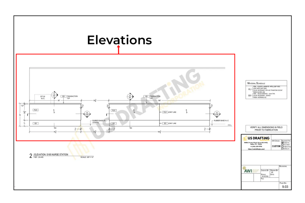
An elevation view shows the millwork from the front, giving a clear understanding of height, proportions, and design details. It helps fabricators and installers see how the final piece will look when installed.
For instance, an elevation of this nurse station shows the transaction top, rubber base, and material specifications. These details are critical to ensuring that everything aligns properly during construction.
Sections and Details
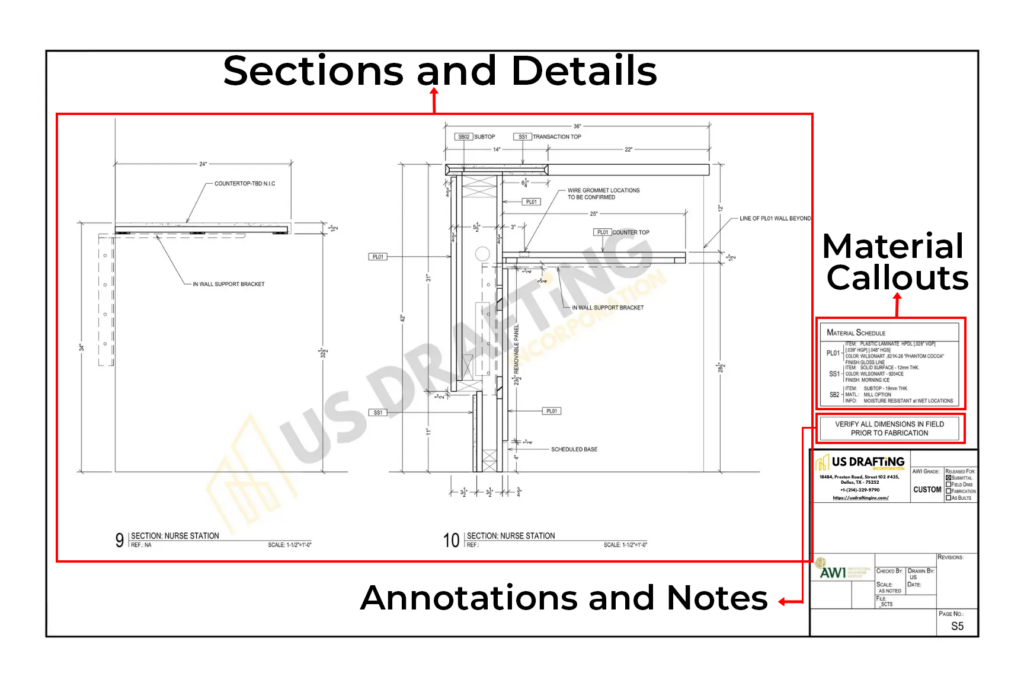
A section view is a cut-through drawing that reveals the internal structure of the millwork. It helps explain how different parts come together, including materials, supports, and fasteners.
For example, a section of the nurse station shows the countertop thickness, in-wall support brackets, and scheduled base. These details are essential for fabricators and installers to follow precise construction methods. Section views also highlight hidden elements that may not be visible in plan or elevation views.
Material Callouts
The material schedule lists the materials used in the project, including their specifications, colors, finishes, and thicknesses. In the above example, each material is identified by a code (e.g., PL1, SS1) that matches the callouts in the drawings.
- PL1 (Plastic Laminate): Specifies thickness options and color (e.g., Wilsonart 821K-28 “Phantom Cocoa” with a gloss finish).
- SS1 (Solid Surface): Defines thickness, color (e.g., Wilsonart 920ACE), and finish (e.g., Morning Ice).
These material callouts help fabricators and installers to use the correct materials, maintaining consistency and quality throughout the project.
Annotations and Notes
Annotations and notes provide important instructions to avoid errors during fabrication and installation.
For example, the note “VERIFY ALL DIMENSIONS IN FIELD PRIOR TO FABRICATION“ reminds teams to confirm actual site measurements before cutting or assembling materials. This step is critical, especially for custom millwork.
Now we have an idea of the elements of millwork drawings, let’s understand the steps to read the millwork shop drawings.
Steps to Read Millwork Shop Drawings
Reading millwork shop drawings is important for fabricators, contractors, and installers. These drawings provide exact details for construction and installation. Here’s how to read them step by step:

Step 1: Understand the Scale
Check the scale of the drawing, usually noted in the title block or near the view. Common scales include 1/4″ = 1′-0″ or 1/2″ = 1′-0″, meaning every quarter or half-inch on the drawing represents one foot in real life. Knowing the scale helps interpret dimensions correctly.
Step 2: Follow the Views
Millwork drawings include different views to show the full picture:
- Plan View (Top-down layout) – Shows how millwork fits in the space.
- Elevations (Front-facing view) – Displays height, proportions, and design details.
- Sections (Cut-through view) – Reveals internal structure, materials, and connections.
- Details (Close-up drawings) – Highlight specific construction elements.
Start with the plan view, then move to elevations, sections, and details for a complete understanding.
Step 3: Look for Dimensions & Tolerances
Millwork drawings are full of measurements. Check lengths, widths, and heights to match site conditions. Pay attention to tolerances—small adjustments allowed in fabrication to account for installation flexibility.
Step 4: Check Materials & Finishes
Materials are labeled with codes like PL1 (Plastic Laminate) or SS1 (Solid Surface). Refer to the material schedule to confirm thickness, color, and finish. Using the correct materials helps maintain design consistency and quality.
Step 5: Understand Symbols & Abbreviations
Shop drawings use standard symbols and abbreviations to simplify communication. Some common ones include:
- CL = Centerline
- PL = Plywood
- Ø = Diameter
- TYP = Typical (applies to multiple similar elements)
Learning these symbols helps in reading the drawings accurately.
Step 6: Review Annotations & Notes
Annotations provide instructions for fabrication and installation. Notes like “Verify all dimensions in the field prior to fabrication“ remind teams to check site conditions before cutting materials. These details help avoid errors and adjustments later.
Step 7: Identify Hardware & Fasteners
Some drawings include hardware specifications, such as hinges, drawer slides, or screws. Checking these details helps in ordering the right components and preparing for assembly.
Bringing It All Together

Reading millwork shop drawings becomes much easier when you break them down into steps. Checking the scale, following the views, reviewing dimensions, and understanding materials is key to avoiding mistakes. So, clear millwork shop drawings lead to better fabrication and installation.
For precise and professional millwork shop drawings, US Drafting Inc. is here to help. Our team delivers detailed, accurate, and industry-standard drawings to keep your project on track.
Note: The information in this article is based on industry knowledge and best practices. Project requirements may vary, so always review drawings based on your specific needs.


1 Comment